


Senva TG Series refrigerant sensors are a great solution for refrigerant leak detection in many applications. It can be ordered as individually calibrated R134A or R410A sensors or any combination with CO or NO2 sensors. Buy pre-calibrated for R134A or R410A or factory calibrate to any refrigerant including R134A, R410A, R407C, R404A, R22, R123. The analog output model features 2 outputs that support daisy chain wiring - multiple sensors may be used in a parallel sequence (0-10V) for cost-effective coverage of large areas. The unit can also act as a stand-alone controller, utilizing the relay for exhaust fan operation or the output for direct control of a VFD. The BACnet/Modbus model supports one unit of MS/TP & Modbus network communication. Standard features include network auto-configuration, a programmable fan relay, LED indicators, an integrated display, and an audible alarm.
- A2L and A3 leak detection in mechanical rooms
- Pre-calibrated for R134A or R410A or factory calibrate to any refrigerant including R134A, R410A, R407C, R404A, R22, R123 and most A2L gases
- Monitor multiple gases with one mounted unit
- Alert occupants of elevated gas levels
- Directly control exhaust fans

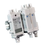
| Power Supply |
15-30VDC/24VAC(1), 4W max, 160mA max |
|
| Wiring |
Conductor |
14-24 AWG, Minimum 600V, 75°C |
|
Analog Outputs |
2 programmable outputs |
0-10V (default), 0-5V, 1-5V, 4-20mA (menu selectable) |
|
BACnet/Modbus |
Protocol RS-485 |
BACnet MS/TP, Modbus RTU, Modbus ASCII |
|
Fan Relay |
Fan relay characteristics |
N.C. 1A@24/30VDC (50/60Hz) (no mains connection) |
|
Alarm Relay |
Alarm relay characteristics |
N.C. 1A@24/30VDC (50/60Hz) (no mains connection) |
|
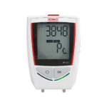
Display |
3-1/2 digit LCD |
Indicates CO ppm, NO2 ppm, Temp (menu selectable) (menu selectable) |
|
LEDs |
Green, Yellow, Red |
Green = Normal, Yellow = Relay, Red = Alarm |
|
Audible Alarm |
85dB @4" Piezo transducer |
30 minutes above alarm setpoint per UL2075 (menu selectable) |
|
CO Sensor Performance (6) |
Type |
Electrochemical |
|
NO2 Sensor Performance (7) |
Type |
Electrochemical |
|
CO2 Sensor Performance |
Type |
Non-dispersive Infrared (NDIR) |
|
Methane/Propane/Hydrogen Sensor Performance |
Type |
Catalytic |
|
Oxygen Sensor Performance |
Type |
Electrochemical |
|
Hydrogen Sulfide (H2S) Sensor Performance |
Type |
Electrochemical |
|
Ammonia (NH3) Sensor Performance |
Type |
Electrochemical |
|
Refrigerant Sensor Performance |
Type |
MOS |
|
Operating Environment |
Temperature, Operational(4) |
-20 to 50oC (MOS rated down to -30°C; CO2 versions rated to -40oC) |
|
Enclosure |
Material |
ABS/Polycarbonate |
|
Enclosure |
Material |
Powder-coated steel/acrylic |
|
Agency |
Compliance |
UL61010-1 Listed UL, cUL, CE |
- One side of transformer secondary is connected to signal common. Dedicated transformer is recommended. No mains circuit connection allowed. In addition, it is required to use an isolated power supply that is certified by a national or international standard (i.e. UL). Use of a Class 2 LPS power supply or greater is required.
- R134A sensor is factory calibrated to R134A gas but may be used as a general-purpose refrigerant sensor. Sensitivity to some other gases can be found in the installation manual. Actual response may vary depending on installation. For more accurate response to a specific gas, a unit may be field calibrated.
- These gases may be detected by the sensor, but sensitivity curves are not available at this time.
- Accuracy of CO2 reading may be reduced at temperatures below 14ºF (-10°C).
- Refrigerant sensors have been tested to perform at this altitude. To maintain accuracy spec, a field calibration is recommended.
- Carbon Monoxide full scale is 1000ppm.
- Nitrogen Dioxide full scale is 30ppm.
- CO2 sensor is equipped with a heater to account for temperatures down to -40°C.
- It is not recommended to de-activate ABC (auto-calibration) except for continuously occupied spaces or greednhouses. Drift ratings may vary based on encironment.
- Combination CO/Methane, CO/Propane, or CO/Refrigerant sensors should be mounted according to Propane/Methane/Refrigerant recommendations. Consult factory for other comvinations. Mounting height recommendations may be adjusted according to installation. Ensure sensor is accessible for maintenance and target gas has unobstructed access to sensor. Mount in accordance with ANSI/NFPA 70 and NEC or CEC.
- A bump test involves exposing the sensor to a reference gas and detecting the sensor’s response. If sensor response is out of accuracy range, recalibration or replacement of the sensor element may be necessary.


 Humidification
 Dehumidification
 HVAC Measuring instruments
 HVAC Sensors & Field Devices
 Air Particles Counting
 Microbial Air Sampler